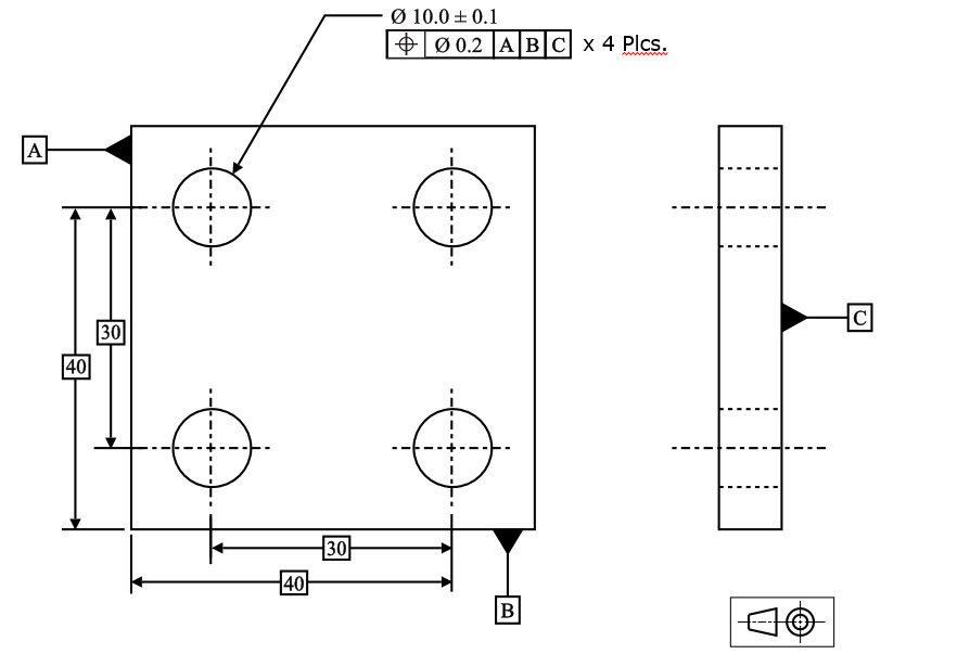
Ok, I have read the post regarding this so called argument that my boss and I got into today. He told me that you cannot measure true position in 3 axis, as I told him he was wrong. I know it depends on the way the FCF calls it out, but I tried to explain to him that it is possible to measure TP in 3 axis.I have seen the formulas, so I know it's possible. I just wish I could get one of you gurus to reply back explaining that it is possible and why. I see the picture but he does not.
- Composite True Position Calculator
- True Position Calculator
- Manual Calculation Of True Position Technologies Valencia Ca
I do not like to get into pissing matches with upper management, but I have learned a h.ll of alot from you guys, and I know this is possible. So if one of you fine gentleman can back me up on this, I would very much appreciate it. Thank you very much.Now I am going to get a cold beer. John,The part is a square block with a counter bore in the middle of it. The drawing is asking position of the 'central point ' of the cylinder ( meaning center of x,y,z) of the cylinder to datums, a-b-c. A datum in x, b datum in y, and c datum in z from the bottom of the part.
Composite True Position Calculator
Basically it's a point that has been established within the cylinder with basic dimension to all 3 axis noted as datums. It only makes sense to me that if that centroid point has been given basic dimensions from 3 axis that are labled datums a-b-c-, that you should be able to calculate it as all 3.
Thank you gentleman.I rest my case.It's so hard to explain things to people that just don't get the picture. I don't blame them for their ignorance, I do blame them for not at least listening to what is being explained and not trying to understand what is real and what is their personal concept of positioning. Yea, in general, as my boss stated, true position is is 2 axis. I agree, but there is the instance ( be it very uncommon) that position can be measured 3d. Man, cmm concept vs.

Interpetation of the drawing is everything. I am still learning, but at least I am learning from the best. Thank you guys. It's our working together to teach one another that makes this the best forum out there. I'll say it again.if it was not for the guys with the high experience helping us new guys, nobody would gain anything. Because the dmis manual is not written like ' windows for dummies'.Thanks again,Patrick.
John,the part is a square block with a counter bore in the middle of it. The drawing is asking position of the 'central point ' of the cylinder ( meaning center of x,y,z) of the cylinder to datums, a-b-c. A datum in x, b datum in y, and c datum in z from the bottom of the part. Basically it's a point that has been established within the cylinder with basic dimension to all 3 axis noted as datums. It only makes sense to me that if that centroid point has been given basic dimensions from 3 axis that are labled datums a-b-c-, that you should be able to calculate it as all 3. Is the cylinder normal to the datum axes? If it is at an angle/compound angle then it's not a 3D TP even though it's a 3D basic dim.
Called out.PC-DMIS does not support this type of TP, you must report XYZ and IJK direction of cosine for that cylinder separately, for TP you must rotate and translate to theoretical position to that cylinder but measure it as a circle at both ends. With same set of basic dim's also apply to the adjacent surface of that cylinder to control the elevation and angulations of that surface, there should be profile called out for that surface.
True Position Calculator
Basically, what is called out really appears to be a target point in the center of a cylinder, which is perp. To the datum-A- surface.
There is a ring that is cut in the same cylinder, basically at the same basic height as the target point. I think they want this so called target point of the cylinder to be within an area, so the mating part will fit. Very strange indeed I know. Usually I don't see things of this nature on a drawing. I called and left a message to speak to someone at our customers facility, to go over what their really looking for. I suspect it is in error on their part, as the sketch was produced fairly quickly, with no sign offs of approval by someone else that had examined the sketch to insure it was correct.
Manual Calculation Of True Position Technologies Valencia Ca
To me, I would think the drawing should have the basic tolerancing in 2 axis, with the 3rd axis toleranced as ±. But I am not a rocket scientist on GD&T.I really just wanted to find out if it was possible to actual measure TP in 3 axis. As, I see it can be done in RFS using the legacy dimensions.
Thanks again for all the help and comments. I appreciate it.